Chase Schober: Difference between revisions
No edit summary |
No edit summary |
||
| (32 intermediate revisions by the same user not shown) | |||
| Line 1: | Line 1: | ||
[[File:Chase_1.jpg|400px]] | [[File:Chase Tormach.jpg|600px]] [[File:Chase_1.jpg|400px]] | ||
'''''Machining Supervisor''''' | |||
''''' | |||
'''Email:''' cschober@tulane.edu | '''Email:''' cschober@tulane.edu | ||
'''Phone:''' ( | '''Phone:''' (985) 326-1792 | ||
'''Major:''' Engineering Physics | '''Major:''' Engineering Physics | ||
'''Graduation Date:''' May, 2018 | '''Graduation Date:''' May, 2018 | ||
==Projects== | ==Projects== | ||
*'''CNC Mill''' | *'''CNC Mill''' | ||
During the summer of 2017, I logged over 300 hours on the Tormach PCNC 770 mill. As the two students who had experience in working the mill both graduated, I trained myself on the machine through meticulous reserach and calculated trial and error. After a month, I began to feel comfortable with the various end mills, CAM operations on Fusion 360, and the intense concentration required to operate the powerful machine. Gradually, I began to machine custom aluminum parts for several research labs on campus to gain experience and by the end of the summer, I had made over 30 aluminum parts for four Tulane research groups. This work has continued into my senior year as I continue to work closely with two of the labs as their lab engineer and lab machinist respectively. Here are some of the more comprehensive projects that I worked on with a description of their process and purpose. | |||
[[File:Chase CNC MIll.jpeg|center|500px]] | |||
'''Tulane University Biomechanics of Growth and Remodeling Lab:''' | '''Tulane University Biomechanics of Growth and Remodeling Lab:''' | ||
This lab approached me with the engineering plans for an adjustable cruciform to assist in his bio-medical research. They provided me with CAD models of four "slider" parts and one "stamp base". I imported them into Fusion 360, wrote the CAM, and machined the parts using the Tormach PCNC 770. Becuase of the locomotive nature of the sliders, each of their tolerances was ± .002". Each of the stamps required machining on both the top and bottom surface and so were flipped in the vice halfway through the operation. This was an excellent experience in standardizing my measurement procedure and performing the operation so that the two cuts met each other | This lab approached me with the engineering plans for an adjustable cruciform to assist in his bio-medical research. They provided me with CAD models of four "slider" parts and one "stamp base". I imported them into Fusion 360, wrote the CAM, and machined the parts using the Tormach PCNC 770. Becuase of the locomotive nature of the sliders, each of their tolerances was ± .002". Each of the stamps required machining on both the top and bottom surface and so were flipped in the vice halfway through the operation. This was an excellent experience in standardizing my measurement procedure and performing the operation so that the two cuts met each other seamlessly. | ||
The stamp base required the use of a T-slotter to route the hole for the sliders. I researched the appropriate feeds and speeds of the new tool and manipulated the CAM to produce a cut within specification. This part also required a vice flip in order to machine both sides. | The stamp base required the use of a T-slotter to route the hole for the sliders. I researched the appropriate feeds and speeds of the new tool and manipulated the CAM to produce a cut within specification. This part also required a vice flip in order to machine both sides. | ||
| Line 27: | Line 26: | ||
The cruciform, made of the five machined components, is being actively used by the Biomechanics of Growth and Remodeling Lab at Tulane University. Before we came into contact, a machining company had quoted their lab $585.00 for the five parts. | The cruciform, made of the five machined components, is being actively used by the Biomechanics of Growth and Remodeling Lab at Tulane University. Before we came into contact, a machining company had quoted their lab $585.00 for the five parts. | ||
[[File:Chase Schuster 2.png| | [[File:Chase Schuster 2.png|500px]] [[File:Chase Schuster 3.jpeg|300px]] [[File:Chase Schuster 1.jpeg|300px]] | ||
| Line 36: | Line 35: | ||
1) This 4.2" diameter aluminum part contained 30 separate holes with an inside profile. The operations required were straightforward and consisted of milling the stock to size, facing each profile, and then spot drilling each hole. Then, the 30 holes were drilled (requiring three separate twist drill bits). After that, a 3/16", 2 flute end mill was used to perform an adaptive cut on the inside profile. Following the adaptive, the same end mill cleaned up the profile with a contour operation. Finally, an outside contour operation was performed to cut the circular piece out of the rectangular stock. Finish work was performed on a polishing wheel. I machined a duplicate of this part several weeks after to expedite prototyping. | 1) This 4.2" diameter aluminum part contained 30 separate holes with an inside profile. The operations required were straightforward and consisted of milling the stock to size, facing each profile, and then spot drilling each hole. Then, the 30 holes were drilled (requiring three separate twist drill bits). After that, a 3/16", 2 flute end mill was used to perform an adaptive cut on the inside profile. Following the adaptive, the same end mill cleaned up the profile with a contour operation. Finally, an outside contour operation was performed to cut the circular piece out of the rectangular stock. Finish work was performed on a polishing wheel. I machined a duplicate of this part several weeks after to expedite prototyping. | ||
[[File:Chase Escarra 1.jpeg|400px]] | [[File:Chase Escarra 1.jpeg|400px]] | ||
2) This 4.2" diameter aluminum part required tight tolerances for the six external profiles. As it was being used as a stamp to form a polymer mold, the height of the profile was required to be 125 microns ± 25 microns. This was especially difficult because the thickness of the part was .118" and was sensitive to vice buckling as a result. Finally, the grooves in between the profiles were 1 mm wide and required the use of a .5mm end mill. After one failed attempt (as a result of the vice bucking), I met the specifications and the part is now being used to produce polymer molds. | 2) This 4.2" diameter aluminum part required tight tolerances for the six external profiles. As it was being used as a stamp to form a polymer mold, the height of the profile was required to be 125 microns ± 25 microns. This was especially difficult because the thickness of the part was .118" and was sensitive to vice buckling as a result. Finally, the grooves in between the profiles were 1 mm wide and required the use of a .5mm end mill. After one failed attempt (as a result of the vice bucking), I met the specifications and the part is now being used to produce polymer molds. | ||
[[File:Chase Escarra 2.jpeg|400px]] | [[File:Chase Escarra 2.jpeg|400px]] | ||
3) This 4.2" diameter aluminum part contained 30 separate holes and seven 125 micron-deep pockets. As it closely resembles a combination of the two previous parts, I was comfortable with the operations and their tolerances. | 3) This 4.2" diameter aluminum part contained 30 separate holes and seven 125 micron-deep pockets. As it closely resembles a combination of the two previous parts, I was comfortable with the operations and their tolerances. | ||
[[File:2017-08-16 20.03.53.jpg|400px]] | [[File:2017-08-16 20.03.53.jpg|400px]] | ||
4) | 4) | ||
[[File:Chase Escarra 4.jpeg|400px]] | [[File:Chase Escarra 4.jpeg|400px]] | ||
5) I have been heavily involved in the modification of a glass-cutting diamond saw. In addition to machining several iterations of the blade bushing (shown below), I machined the aluminum saw support and am currently working on a safety enclosure and fluid cooling system. | 5) I have been heavily involved in the modification of a glass-cutting diamond saw. In addition to machining several iterations of the blade bushing (shown below), I machined the aluminum saw support and am currently working on a safety enclosure and fluid cooling system. | ||
[[File:Chase Escarra 5.jpeg|400px]] | [[File:Chase Escarra 5.jpeg|400px]] | ||
'''Tulane University Femtosecond & Terahertz Spectroscopy Laboratory''' | |||
[[File:Schober Jimmy 1.jpeg|350px]] | |||
[[File:Chase Jimmy 2.jpeg|350px]] | |||
[[File:Chase Jimmy 3.jpeg|350px]] | |||
'''Tulane University Reed Macromolecular Research Group:''' | |||
I was approached by a graduate student in Professor Reed's lab and asked to manufacture specialized aluminum cuvette caps. Proteins in solution (intended for pharmaceutical development) tend to adsorb to the walls of the cuvette or to the stir bar and aggregate upon agitation. These caps allow the researchers to suspend a stir bar above the bottom of the cuvette to remove the solid-solid interfacial contact while monitoring aggregation caused by agitation via light scattering. We milled nine caps out of a .75" of aluminum plate and hit our tolerance of ± .002". | |||
[[File:Chase Reed 2.jpeg|Center|400px]] [[File:Chase Reed 1.jpeg|600px]] | |||
| Line 59: | Line 73: | ||
In addition to my work with the Tormach PCNC 770 mill, I also had the chance to operate a Tormach 15L Slant Pro CNC Lathe. I set all of the tool offsets, troubleshooted several coolant and oil pump issues, and then developed an extensive training manual to institutionalize the experience I had gained through use. Here are some projects that I have undertaken on the lathe. | In addition to my work with the Tormach PCNC 770 mill, I also had the chance to operate a Tormach 15L Slant Pro CNC Lathe. I set all of the tool offsets, troubleshooted several coolant and oil pump issues, and then developed an extensive training manual to institutionalize the experience I had gained through use. Here are some projects that I have undertaken on the lathe. | ||
[[File:Chase Lathe.jpg|center|500px]] | |||
'''Tulane University Cellular Biomechanics and Biotransport Lab:''' | '''Tulane University Cellular Biomechanics and Biotransport Lab:''' | ||
| Line 67: | Line 81: | ||
[[File:Chase Jarrod 1.jpeg|400px]] | [[File:Chase Jarrod 1.jpeg|400px]] | ||
[[File:Chase Jarrod 3.png|400px]] | [[File:Chase Jarrod 3.png|400px]] | ||
'''Lathe Training Documentation:''' | |||
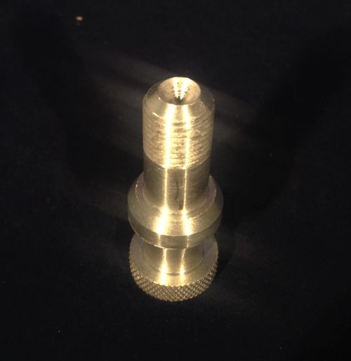
A large portion of my recent work on the lathe has been to compile a comprehensive training document. In this 37-page step-by-step manual, I thoroughly explain the operations of the lathe through detailed diagrams and user instruction. By the end of the training, the user will have made the widget shown below out of 1" aluminum stock using the Conversational mode of the Tormach lathe. | |||
'''[https://tulane.box.com/s/7npmpsbj1yfwr7ezamiqlu98td63da24 Lathe Training Walkthrough]''' | |||
[[File:Lathe Training Part.jpeg|500px]] | |||
Latest revision as of 23:06, 12 February 2018
Machining Supervisor
Email: cschober@tulane.edu
Phone: (985) 326-1792
Major: Engineering Physics
Graduation Date: May, 2018
Projects
- CNC Mill
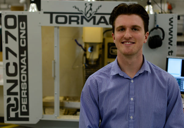
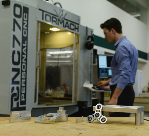
During the summer of 2017, I logged over 300 hours on the Tormach PCNC 770 mill. As the two students who had experience in working the mill both graduated, I trained myself on the machine through meticulous reserach and calculated trial and error. After a month, I began to feel comfortable with the various end mills, CAM operations on Fusion 360, and the intense concentration required to operate the powerful machine. Gradually, I began to machine custom aluminum parts for several research labs on campus to gain experience and by the end of the summer, I had made over 30 aluminum parts for four Tulane research groups. This work has continued into my senior year as I continue to work closely with two of the labs as their lab engineer and lab machinist respectively. Here are some of the more comprehensive projects that I worked on with a description of their process and purpose.
Tulane University Biomechanics of Growth and Remodeling Lab:
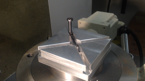
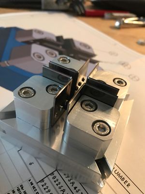
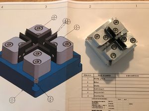
This lab approached me with the engineering plans for an adjustable cruciform to assist in his bio-medical research. They provided me with CAD models of four "slider" parts and one "stamp base". I imported them into Fusion 360, wrote the CAM, and machined the parts using the Tormach PCNC 770. Becuase of the locomotive nature of the sliders, each of their tolerances was ± .002". Each of the stamps required machining on both the top and bottom surface and so were flipped in the vice halfway through the operation. This was an excellent experience in standardizing my measurement procedure and performing the operation so that the two cuts met each other seamlessly.
The stamp base required the use of a T-slotter to route the hole for the sliders. I researched the appropriate feeds and speeds of the new tool and manipulated the CAM to produce a cut within specification. This part also required a vice flip in order to machine both sides.
The cruciform, made of the five machined components, is being actively used by the Biomechanics of Growth and Remodeling Lab at Tulane University. Before we came into contact, a machining company had quoted their lab $585.00 for the five parts.
Tulane University Photonic Materials and Device Lab:
I was approached by this lab at the beginning of the summer and provided them with access to the 3D printers and laser engravers in the MakerSpace. As I began to train on the CNC mill, they took interest in my services and hired me as their lab machinist. The bulk of their demand has been aluminum parts for the Full Spectrum Solar Energy Conversion system they are developing. Below are some of the more complex parts that I have machined for them with a technical description.
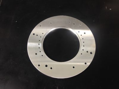
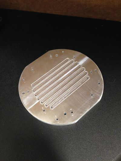
1) This 4.2" diameter aluminum part contained 30 separate holes with an inside profile. The operations required were straightforward and consisted of milling the stock to size, facing each profile, and then spot drilling each hole. Then, the 30 holes were drilled (requiring three separate twist drill bits). After that, a 3/16", 2 flute end mill was used to perform an adaptive cut on the inside profile. Following the adaptive, the same end mill cleaned up the profile with a contour operation. Finally, an outside contour operation was performed to cut the circular piece out of the rectangular stock. Finish work was performed on a polishing wheel. I machined a duplicate of this part several weeks after to expedite prototyping.
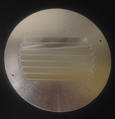
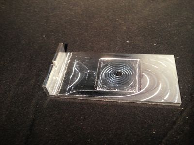
2) This 4.2" diameter aluminum part required tight tolerances for the six external profiles. As it was being used as a stamp to form a polymer mold, the height of the profile was required to be 125 microns ± 25 microns. This was especially difficult because the thickness of the part was .118" and was sensitive to vice buckling as a result. Finally, the grooves in between the profiles were 1 mm wide and required the use of a .5mm end mill. After one failed attempt (as a result of the vice bucking), I met the specifications and the part is now being used to produce polymer molds.
3) This 4.2" diameter aluminum part contained 30 separate holes and seven 125 micron-deep pockets. As it closely resembles a combination of the two previous parts, I was comfortable with the operations and their tolerances.
4)
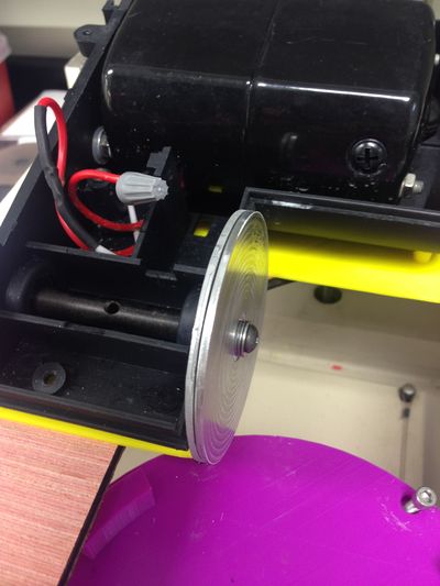
5) I have been heavily involved in the modification of a glass-cutting diamond saw. In addition to machining several iterations of the blade bushing (shown below), I machined the aluminum saw support and am currently working on a safety enclosure and fluid cooling system.
Tulane University Femtosecond & Terahertz Spectroscopy Laboratory
Tulane University Reed Macromolecular Research Group:
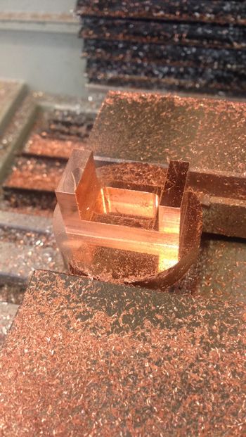
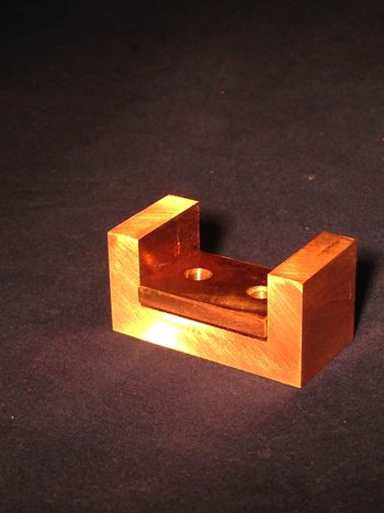
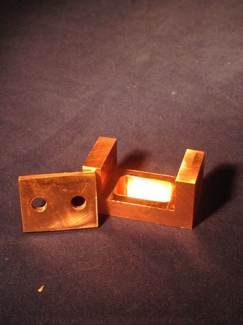
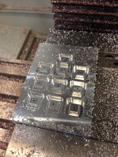
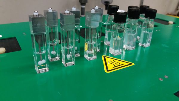
I was approached by a graduate student in Professor Reed's lab and asked to manufacture specialized aluminum cuvette caps. Proteins in solution (intended for pharmaceutical development) tend to adsorb to the walls of the cuvette or to the stir bar and aggregate upon agitation. These caps allow the researchers to suspend a stir bar above the bottom of the cuvette to remove the solid-solid interfacial contact while monitoring aggregation caused by agitation via light scattering. We milled nine caps out of a .75" of aluminum plate and hit our tolerance of ± .002".
- CNC Lathe
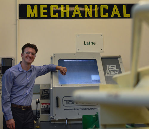
In addition to my work with the Tormach PCNC 770 mill, I also had the chance to operate a Tormach 15L Slant Pro CNC Lathe. I set all of the tool offsets, troubleshooted several coolant and oil pump issues, and then developed an extensive training manual to institutionalize the experience I had gained through use. Here are some projects that I have undertaken on the lathe.
Tulane University Cellular Biomechanics and Biotransport Lab:
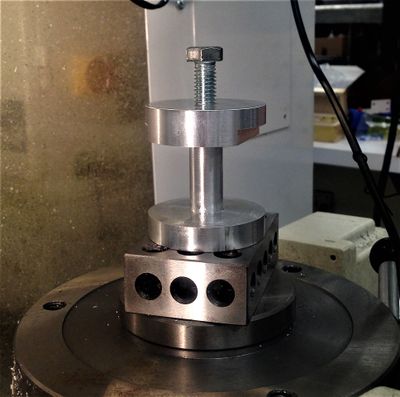
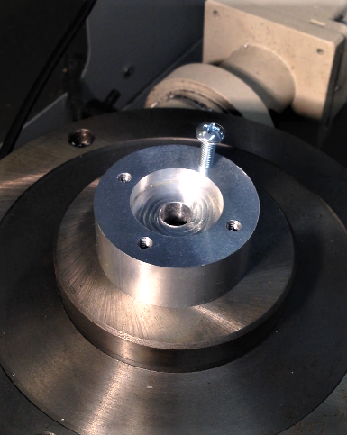
I was approached by several members of a Biomedical lab on campus to make an acoustic device. The apparatus consisted of the two parts shown below in addition to two that were not imaged. Much of the machining was accomplished on the lathe, while several modifying operations were conducted on the mill.
Lathe Training Documentation:
A large portion of my recent work on the lathe has been to compile a comprehensive training document. In this 37-page step-by-step manual, I thoroughly explain the operations of the lathe through detailed diagrams and user instruction. By the end of the training, the user will have made the widget shown below out of 1" aluminum stock using the Conversational mode of the Tormach lathe.
