Generative Design in Fusion 360: Difference between revisions
mNo edit summary |
No edit summary |
||
| (One intermediate revision by the same user not shown) | |||
| Line 1: | Line 1: | ||
[[Image:gendesign.jpeg|425px|right|border|link=]] | |||
[[Image:Thumbnail.png| | [[Image:Thumbnail.png|425px|right|border|link=]] | ||
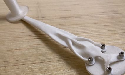
Generative Design is a method for using computer learning to create 3D models that solve solutions to constraints set up by the user. It is relatively complicated, but | Generative Design is a method for using computer learning to create 3D models that solve solutions to constraints set up by the user. It is relatively complicated, but a former Fab Tech, Dylan Lucia, created this video tutorial for using the software. This is offered for free with Education accounts (which is shown in the video, if you don't know about this). Make sure to sign up for an Education account since getting an object out of Generative Design would cost a minimum of $125 without the Education account. | ||
== Videos == | == Videos == | ||
Latest revision as of 17:46, 26 October 2021


Generative Design is a method for using computer learning to create 3D models that solve solutions to constraints set up by the user. It is relatively complicated, but a former Fab Tech, Dylan Lucia, created this video tutorial for using the software. This is offered for free with Education accounts (which is shown in the video, if you don't know about this). Make sure to sign up for an Education account since getting an object out of Generative Design would cost a minimum of $125 without the Education account.
Videos
These are the same video, but one has been commented on in Timelinely with more detailed instructions.
YouTube Video
You may watch the YouTube Video here, with chapters.
Timelinely Video
The Timelinely video has more detailed timestamps, but the player crops the video so you can't see the entire screen. The timestamps are reproduced below.
Chapters and Timestamps
Reproduced here for your convenience.
Chapters
0:00 Introduction
0:16 Signing up for an education account
1:23 Downloading Fusion 360
2:44 Beginning in Fusion 360
6:04 Data panel
6:43 Navigating the window
8:04 Modeling
52:47 Saving
53:09 Evaluating bodies
54:06 Generative design workspace
1:09:57 Generate results
1:11:20 Exploring outcomes
1:14:18 Exporting an outcome/Creating a design
Timestamps
2:18 Sign up for an Autodesk...
6:29 Create a new project...
7:43 Turn on the layout grid and the constrained orbit
8:26 Create a new sketch on the top plane
9:45 Create a ⌀10mm circle at the origin
10:32 Give the center rectangle's edges...
10:47 Finish the sketch
11:32 Extrude the square...
11:52 Rename Body1...
12:51 Create a sketch on the front...
13:48 Project the top edge...
14:30 Create a construction 2 point rectangle...
14:47 Make the edges of the construction...
15:17 Create a construction 3 point circle on...
16:37 Create this shape using sketch lines
17:41 Make the sketch line tangent to the circle
18:49 Apply the 25mm, 5mm, and 8mm...
20:31 Finish the sketch and revolve...
22:31 Create a new sketch on the top face...
25:24 Complete the sketch as shown...
26:11 Extrude the 4 circles through the plate...
28:43 Create a circle 3mm offset from the projected hole...
29:16 Extrude the base of the foot up 2mm...
30:13 Create a circle offset 1mm from the hole on top of the foot body
30:21 Extrude the rest of the foot up 3mm using a join operation.
31:06 Rename Body 2 'Foot'
31:38 Use a circular pattern around the Y axis to create 4 total feet.
33:07 Create an offset plane 5mm above the top of one of the feet.
33:26 Create a sketch on the front plane and project the offset plane into the sketch.
40:50 Complete the sketch as shown for the profile of the handle spindle and finish the sketch
41:19 Rename that body 'HandlePin'
41:53 Apply a 1mm equal distance chamfer to the top edge of HandlePin
42:53 The final handle may be shaped in a more complicated manner like this.
43:03 Create a new sketch in the front plane and project the bottom and top edges of HandlePin into the sketch.
43:45 Create a midpoint construction line between the two projected edges.
46:36 Complete the sketch as shown
47:16 Finish the sketch and revolve it around the construction line to create the handle. Rename the body to 'Handle'
48:49 Create a sketch on the top plane.
49:17 Create a center rectangle that exceeds the size of the arm/handle and finish the sketch.
50:03 Extrude the rectangle up to the bottom face of the small platter with a new body operation and name the body 'Plate'
51:19 Create a new sketch on the front plane and draw a construction line up from the origin.
51:52 Complete the rest of the rectangle as shown.
52:15 Finish the sketch and revolve it with a new body operation and rename the body 'ArmClearance'
53:01 Save your design with the name 'CrankTutorial'
54:15 Change your design workspace to Generative Design
56:27 Click on the Edit Model tool
57:37 Create the stand-in bolt primitive as shown, and do the same for the other 3 stand offs.
1:00:00 Rename the primitives 'Bolt#' as appropriate
1:00:42 Select Handle, ArmClearance, SquareDrive, Plate, and make sure the bolt primitives are selected for Obstacle Geometries
1:01:03 Select HandlePin and all four Feet for Preserve Geometries
1:02:37 Define the four bottom faces of the Feet as Fixed structural constraints.
1:03:53 Clone Load Case1 3 times
1:04:25 Apply the force in Load Case1
1:04:34 Activate Load Case2
1:05:05 Apply the force to Load Case2
1:05:40 Activate Load Case3 and apply the load
1:06:04 Activate Load Case4 and apply the load
1:07:34 Define the Design Goal and Manufacturing
1:08:43 Add materials to the study
1:09:20 Run the pre-check
1:09:55 Run the previewer if you want and if your computer can handle it
1:10:42 Generate the study
1:15:28 Explore the outcomes and create a design from the outcome you like most