Asher Burkin: Difference between revisions
| (27 intermediate revisions by the same user not shown) | |||
| Line 35: | Line 35: | ||
*Programming - Computer Aided Design (CAD), Computer Aided Manufacturing (CAM), [[MATLAB]], [[Water_Jet_Cutter_Training|Intelli-MAX LAYOUT]], [[Water_Jet_Cutter_Training|Intelli-MAX MAKE]], [[Cura]] | *Programming - Computer Aided Design (CAD), Computer Aided Manufacturing (CAM), [[MATLAB]], [[Water_Jet_Cutter_Training|Intelli-MAX LAYOUT]], [[Water_Jet_Cutter_Training|Intelli-MAX MAKE]], [[Cura]] | ||
==Projects== | ==Projects== | ||
| Line 44: | Line 41: | ||
===CNC Mill=== | ===CNC Mill=== | ||
I have been working on creating some of the Titans of CNC | I have been working on creating some of the pieces in the Titans of CNC course to develop a deeper understanding of CAM. When I first started milling, I quickly learned how steep of a learning curve it is. After countless hours of watching videos on how to use CAM, reading the CNC Mill instruction manual, and lots of trial and error, I finally understand the inner workings of this machine and have realized how crucial this understanding is to becoming a good machinist. Through this process I now know what feeds and speeds work best for different tools, the optimal depths of cuts, adaptive clearing methods for pockets and contours, and most importantly, how hard I can push the machine to get the best results. | ||
Below are all the revisions I went through to mill my first piece. | |||
[[File:Titan 1 over time.jpg|400px|]] | [[File:Titan 1 over time.jpg|400px|]] | ||
Below are the final versions of the first and second piece I milled from the Titans of CNC course. | |||
[[File:Titans Mill 1.jpg|300px|left|]] [[File:Titan 2.jpg|300px|Center|]] | [[File:Titans Mill 1.jpg|300px|left|]] [[File:Titan 2.jpg|300px|Center|]] | ||
| Line 57: | Line 54: | ||
====CNC MILL Repair==== | ====CNC MILL Repair==== | ||
I identified, rewired and fixed Tulane Makerspaces' CNC Mill. | I identified, rewired and fixed Tulane Makerspaces' CNC Mill. A few wires had not been secured in the machine because their clamps were broken. The wires pictured below are after I found them. | ||
[[File:Mill Error.jpg|300px|left]] [[File:Mill Wires.jpg|300px|Center]] | [[File:Mill Error.jpg|300px|left]] [[File:Mill Wires.jpg|300px|Center]] | ||
| Line 66: | Line 62: | ||
====[https://www.rubtsovgroup.org/ The Rubtsov Group (Optics Lab)]==== | ====[https://www.rubtsovgroup.org/ The Rubtsov Group (Optics Lab)]==== | ||
This lab came to me because they needed a new part for their to hold a prism accurately. | This lab came to me because they needed a new part for their labs spectrometer to hold a prism accurately. A few graduate students tried to make this part on a manual mill, but they were not getting the tolerances needed. I created the CAM and milled their part, which hit the tolerances. | ||
[[File:Optics Lab in Mill.jpg|300px]] | [[File:Optics Lab in Mill.jpg|300px]] | ||
| Line 74: | Line 70: | ||
====In the lab==== | ====In the lab==== | ||
Below is a picture of the piece I made for the labs spectrometer in action. In the picture you can see the NeHe beam on the surface of the mirrors and on the prism that is being held by the piece I milled. The prism is not clean for alignment purposes. | |||
[[File:Optics lab in lab.jpg|350px]] | [[File:Optics lab in lab.jpg|350px]] | ||
| Line 82: | Line 78: | ||
====[https://kathleengferristulane.wordpress.com/ The Ferris Lab (Ecology Lab)]==== | ====[https://kathleengferristulane.wordpress.com/ The Ferris Lab (Ecology Lab)]==== | ||
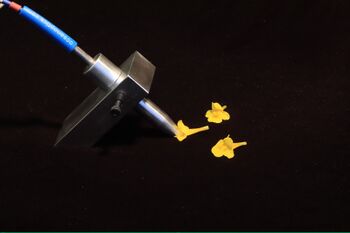
I worked closely with one of | For this project, I worked closely with Bolivar Aponte, one of The Ferris Lab members. Bolivar needed to make something to hold a spectrometry probe in a way that, when taking measurements of flowers, would not crush the petals. The original setup of the probe and holder was a slab of aluminum sitting on top of the flower with a small hole to hold the probe. The probe itself is a cylinder with a small hole at the end where light comes out to take measurements. However, this setup crushed the flower, and made it difficult to position the probe. They also needed a design for the cylindrical holder that would not allow light to penetrate the measurement area. We came up with the solution of angling the larger holder by 45 degrees and creating a cylindrical holder for the probe, minimizing the surface area that makes contact with the flower. This setup not only preserves the flowers better, but also makes it easier to select the sample area. | ||
Making of the probe holder. | |||
[[File:Lathe Part.jpg|300px|left]] [[File:Ecology Lab.jpg|300px|Center]] | [[File:Lathe Part.jpg|300px|left]] [[File:Ecology Lab.jpg|300px|Center]] | ||
Machining all the surfaces flat relative to each other. | |||
[[File:Probe in Mill.jpg|300px|left]] [[File:Probe in Mill after facing.jpg|300px|Center]] | [[File:Probe in Mill.jpg|300px|left]] [[File:Probe in Mill after facing.jpg|300px|Center]] | ||
Final product. We are still in revision and continuing this project to fine tune the process. | |||
[[File:Final Part.jpg|350px|left]] [[File:Final Probe with flowers.jpg|350px|Center]] | [[File:Final Part.jpg|350px|left]] [[File:Final Probe with flowers.jpg|350px|Center]] | ||
===Water Jet=== | ===Water Jet=== | ||
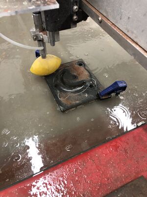
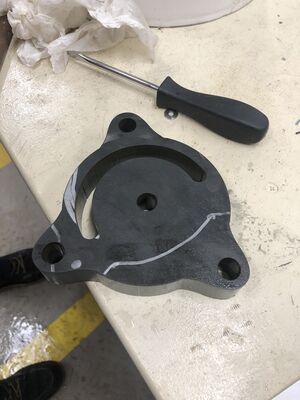
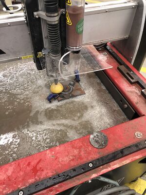
I worked on a project to cut this 1 inch thick, cold rolled slab of steel, into a new base to hold a vice. The entire operation took around 45 minutes. The garnet container needed to be refilled over 10 times and I was constantly checking the orientation of the the water jet cutter. In setting up the program, I had to take into account the kerf of the water as the holes and size of the base needed to run true to the design. I ran a very slow cut for this operation to ensure | I worked on a project to cut this 1 inch thick, cold rolled slab of steel, into a new base to hold a vice. The entire operation took around 45 minutes. The garnet container needed to be refilled over 10 times and I was constantly checking the orientation of the the water jet cutter. In setting up the program, I had to take into account the kerf of the water as the holes and size of the base needed to run true to the design. I ran a very slow cut for this operation to ensure that the deflection of the water, as it first goes through the steel, does not curve too much through the cut. | ||
[[File:Cold rolled steel.jpg|300px|Overall 1in thick cold rolled steel|left|]][[File:Water jet cut for steel vice.jpg|300px|Cutting in water jet|Center|]] | [[File:Cold rolled steel.jpg|300px|Overall 1in thick cold rolled steel|left|]][[File:Water jet cut for steel vice.jpg|300px|Cutting in water jet|Center|]] | ||
| Line 102: | Line 98: | ||
[[File:Vice size comparison.jpg|300px|left]] [[File:Final cut.jpg|300px|Center]] | [[File:Vice size comparison.jpg|300px|left]] [[File:Final cut.jpg|300px|Center]] | ||
====Quick | ====Quick solution during the job==== | ||
[[File:Water Jet shield.jpg|300px]] | [[File:Water Jet shield.jpg|300px]] | ||
===Laser Cutting=== | |||
=== | ====Truss Project==== | ||
I | I made a Pratt Truss. I designed each component and assembled the truss, connecting everything with screws, washers, and nuts. | ||
[[File:Pratt Truss design.png|300px|left]] [[File:Pratt Laser Cut.jpg|300px|Center]] | |||
[[File: | [[File:Pratt Truss Assembled.jpg|350px]] | ||
===Casting=== | |||
I modeled and 3D printed a shape with large draft angles to go through the process of forming the mold and pouring the pewter. I then 3D printed a tiki head to do another casting with the rest of the pewter I had. | |||
[[File:Pewter in cup.jpg|350px]] | |||
[[File:3D print mold.jpg|300px|left]] [[File:Casted.jpg|300px|Center]] | |||
[[File: | |||
[[File: | [[File:Casting.jpg|250px]] [[File:Final Casting.jpg|250px|Center]] | ||
Latest revision as of 03:17, 10 February 2022
MakerSpace Fabrication Technician
Email: aburkin@tulane.edu
Major: Engineering Physics
Certificate: Mechanical Engineering
LinkedIn: in/asherburkin
Profile
Maker Skills
- Machines - CNC Mill, CNC LatheOMAX Water Jet, 3D Printing (Extrusion/SLA), Laser Cutter (Vector/Raster)
- 3D Design - Solidworks, AutoDesk Fusion 360, AutoDesk MeshMixer
- Finite Element Analysis - AutoDesk Fusion 360
- Graphics - Inkscape
- Programming - Computer Aided Design (CAD), Computer Aided Manufacturing (CAM), MATLAB, Intelli-MAX LAYOUT, Intelli-MAX MAKE, Cura
Projects
CNC Mill
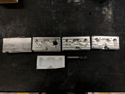
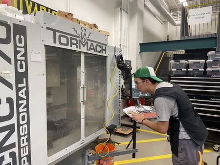
I have been working on creating some of the pieces in the Titans of CNC course to develop a deeper understanding of CAM. When I first started milling, I quickly learned how steep of a learning curve it is. After countless hours of watching videos on how to use CAM, reading the CNC Mill instruction manual, and lots of trial and error, I finally understand the inner workings of this machine and have realized how crucial this understanding is to becoming a good machinist. Through this process I now know what feeds and speeds work best for different tools, the optimal depths of cuts, adaptive clearing methods for pockets and contours, and most importantly, how hard I can push the machine to get the best results.
Below are all the revisions I went through to mill my first piece.
Below are the final versions of the first and second piece I milled from the Titans of CNC course.
CNC MILL Repair
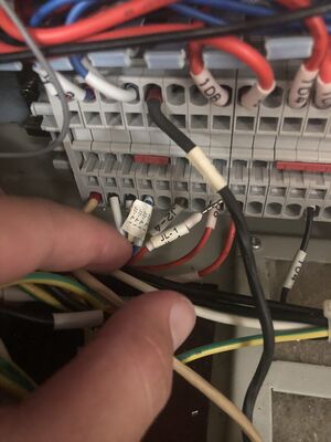
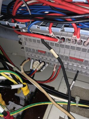
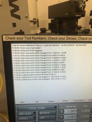
I identified, rewired and fixed Tulane Makerspaces' CNC Mill. A few wires had not been secured in the machine because their clamps were broken. The wires pictured below are after I found them.
The Rubtsov Group (Optics Lab)
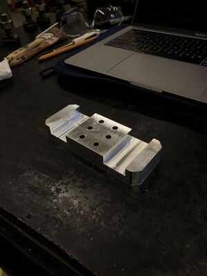
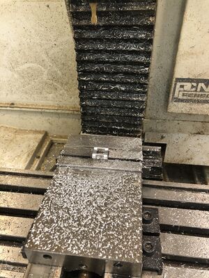
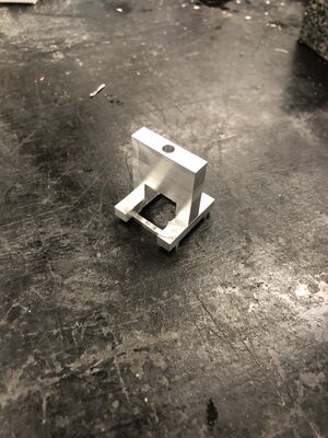
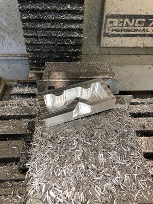
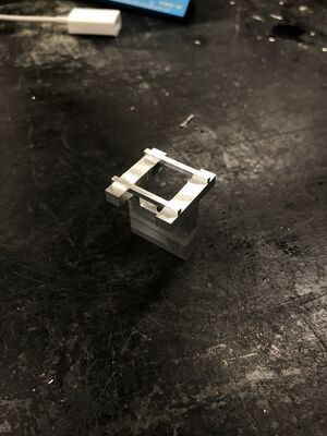
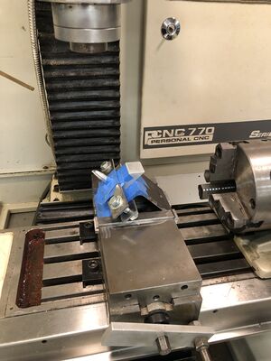
This lab came to me because they needed a new part for their labs spectrometer to hold a prism accurately. A few graduate students tried to make this part on a manual mill, but they were not getting the tolerances needed. I created the CAM and milled their part, which hit the tolerances.
In the lab
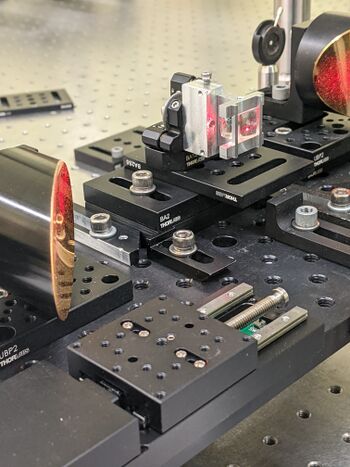
Below is a picture of the piece I made for the labs spectrometer in action. In the picture you can see the NeHe beam on the surface of the mirrors and on the prism that is being held by the piece I milled. The prism is not clean for alignment purposes.
CNC Lathe And CNC Mill
The Ferris Lab (Ecology Lab)
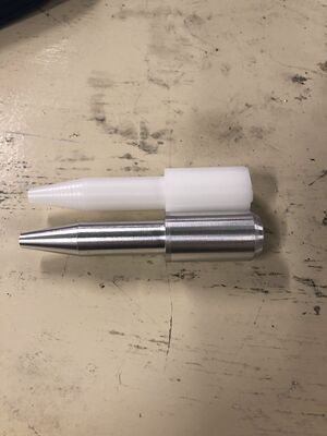
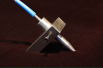
For this project, I worked closely with Bolivar Aponte, one of The Ferris Lab members. Bolivar needed to make something to hold a spectrometry probe in a way that, when taking measurements of flowers, would not crush the petals. The original setup of the probe and holder was a slab of aluminum sitting on top of the flower with a small hole to hold the probe. The probe itself is a cylinder with a small hole at the end where light comes out to take measurements. However, this setup crushed the flower, and made it difficult to position the probe. They also needed a design for the cylindrical holder that would not allow light to penetrate the measurement area. We came up with the solution of angling the larger holder by 45 degrees and creating a cylindrical holder for the probe, minimizing the surface area that makes contact with the flower. This setup not only preserves the flowers better, but also makes it easier to select the sample area.
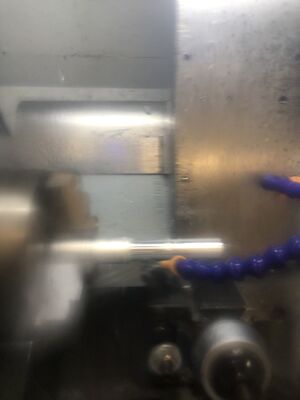
Making of the probe holder.
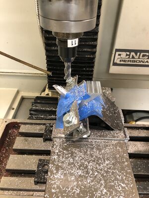
Machining all the surfaces flat relative to each other.
Final product. We are still in revision and continuing this project to fine tune the process.
Water Jet
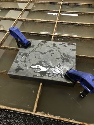
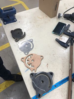
I worked on a project to cut this 1 inch thick, cold rolled slab of steel, into a new base to hold a vice. The entire operation took around 45 minutes. The garnet container needed to be refilled over 10 times and I was constantly checking the orientation of the the water jet cutter. In setting up the program, I had to take into account the kerf of the water as the holes and size of the base needed to run true to the design. I ran a very slow cut for this operation to ensure that the deflection of the water, as it first goes through the steel, does not curve too much through the cut.
Quick solution during the job
Laser Cutting
Truss Project
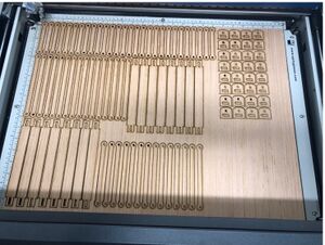
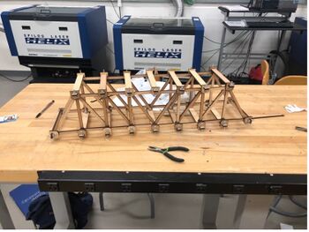
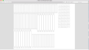
I made a Pratt Truss. I designed each component and assembled the truss, connecting everything with screws, washers, and nuts.
Casting
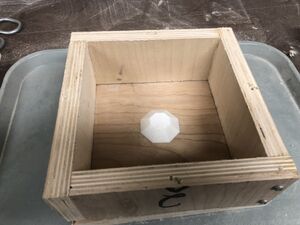
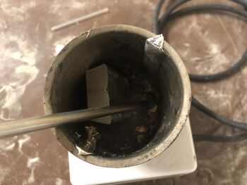
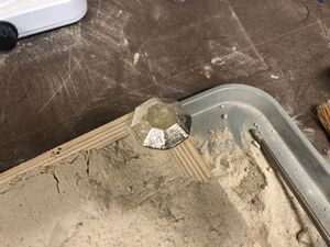
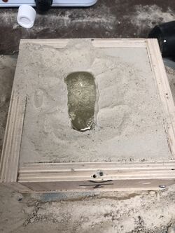
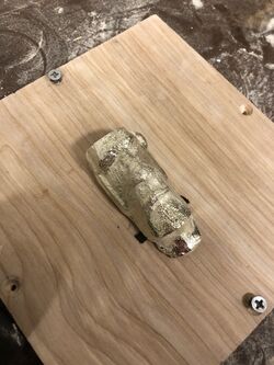
I modeled and 3D printed a shape with large draft angles to go through the process of forming the mold and pouring the pewter. I then 3D printed a tiki head to do another casting with the rest of the pewter I had.
